(Analyze) Shape
Due to the nature of alternating current, half the time the transmitted signal is sent to earth at the grounding device. Due to the grounding device’s proximity, the metal signpost becomes energized (Figures 1-2). Once the signpost is energized, the buried streetlight cable located within a foot of the signpost becomes energized as well.
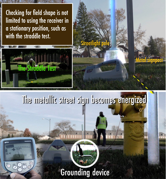
Figures 1-2
Horizontal inspection of the field will oftentimes tell you whether there are other energized lines within the area of your target line (Figure 1). When the instrument is swung to the north (Figure 3), the peak numbers are higher than when the instrument is swung to the south (Figure 4).
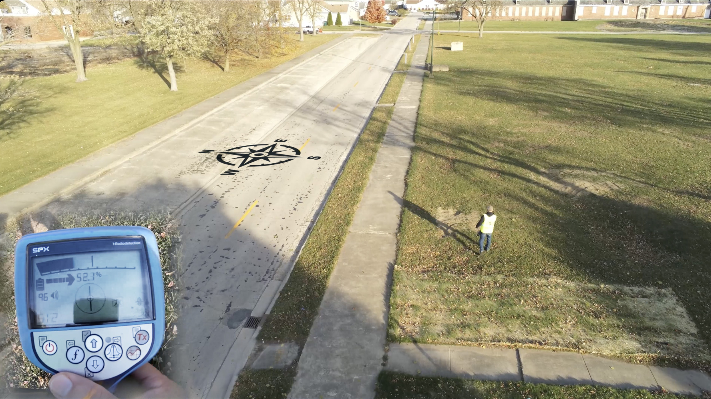
Figure 3
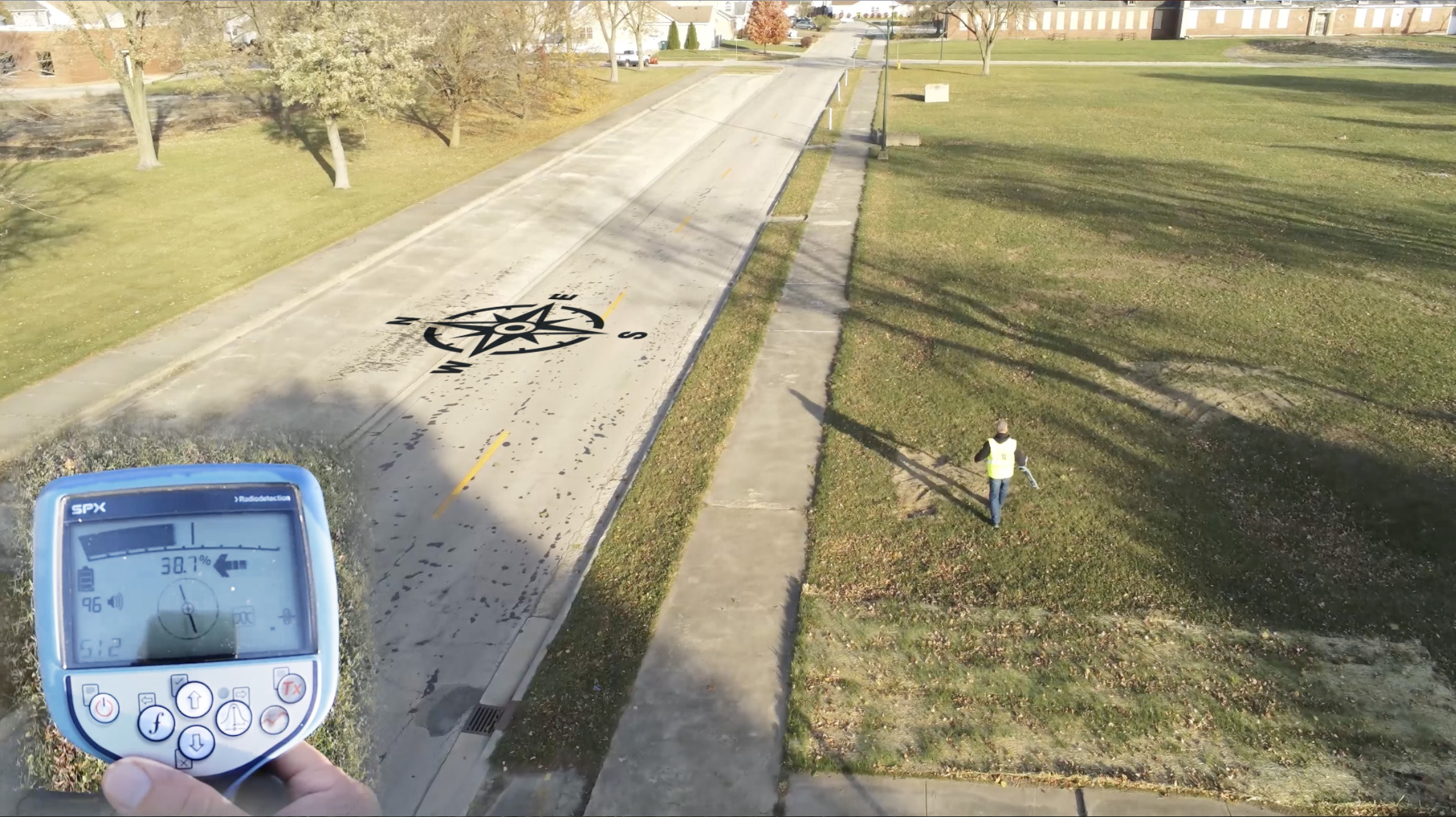
Figure 4
With the receiver being swung to the sides an equal distance, the “straddle test” is performed while walking. Differing audio levels tied to the peak response alert the operator to different peak readings either side of the trace.
Assuming that this is a symmetrical swing of the receiver, the reason why the numbers are higher to the north is that a streetlight cable has some of the transmitter’s energy on it. It’s not enough to make peak and null disagree, but you can see it on the outer edges of the swing. This is a horizontal inspection of the field, and what we’re seeing is known as constructive interference. Current is traveling in the same direction on both the line we’re locating—a water main—as well as the streetlight cable (Figure 5).
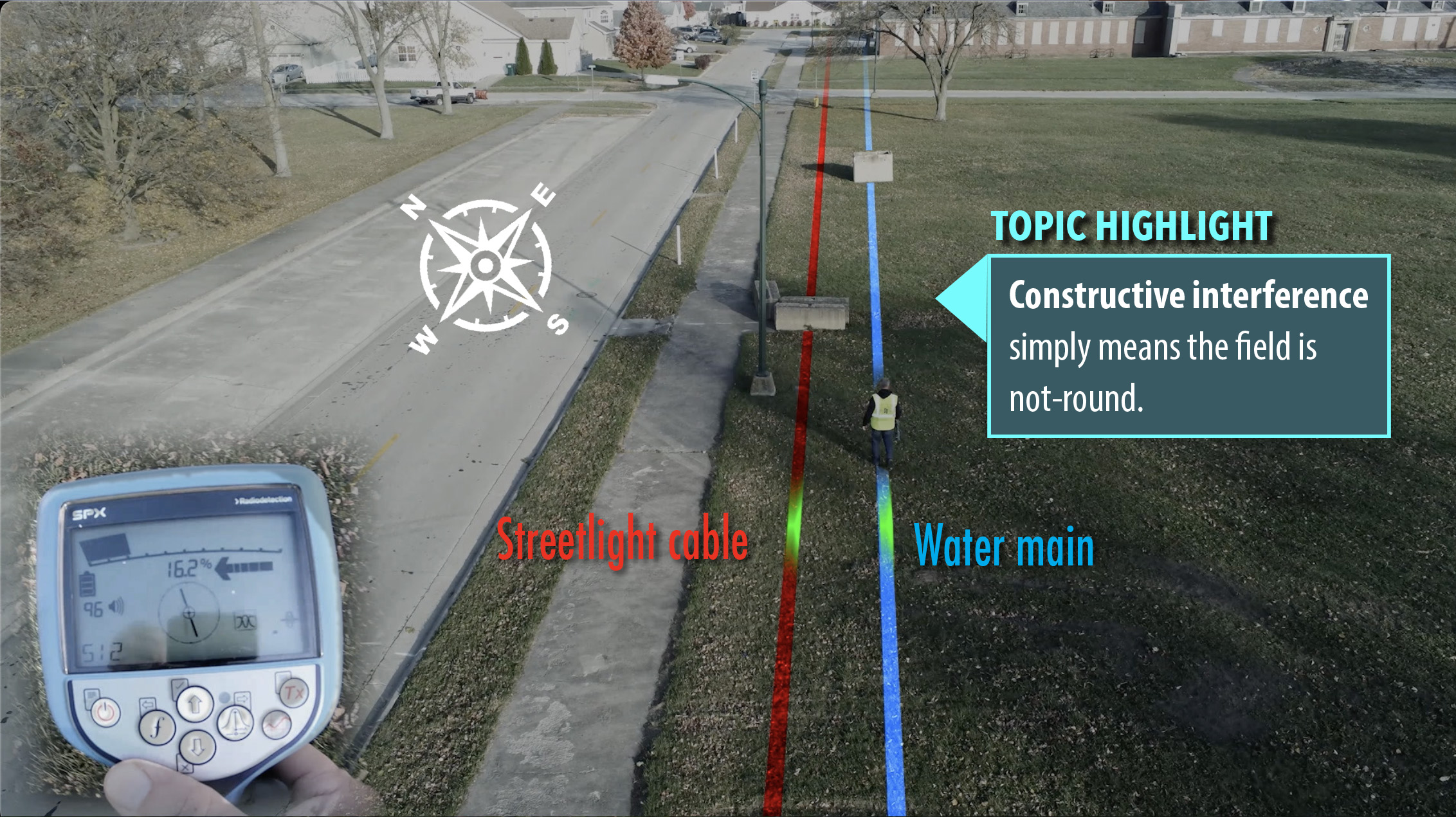
Figure 5
With the signpost energized, it re-radiates signal to the adjacent streetlight cable (Figure 6).
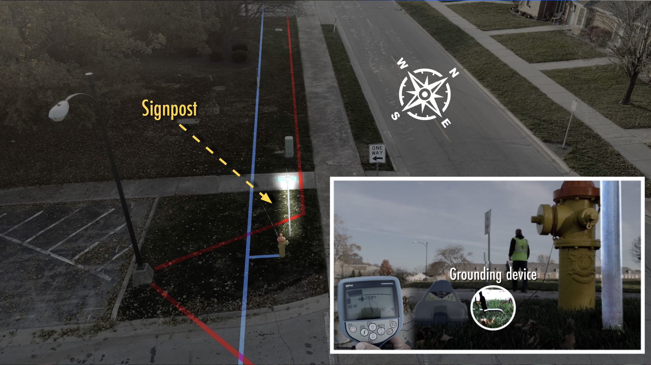
Figure 6
With constructive interference, signal circle values are added (Figures 7-8).
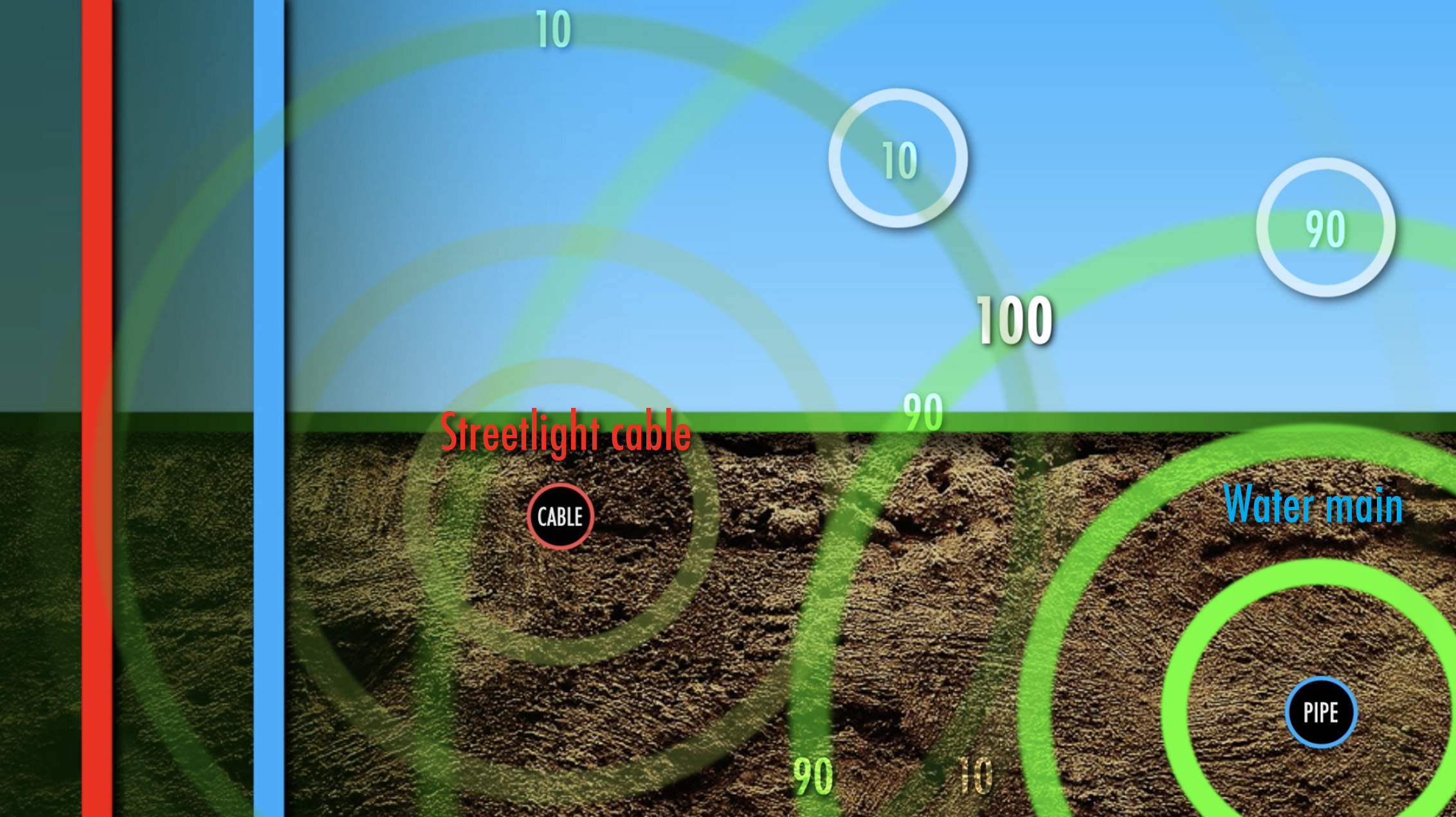
Figure 7
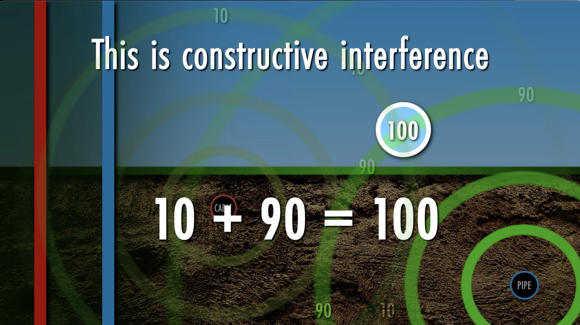
Figure 8
We’re hooked to a steel gas service that’s connected to a steel gas main (Figure 9). Our transmitted frequency is 38 kHz. Once we’re locating the steel main to the west, a cable TV feeder will be located to our south (Figure 10).
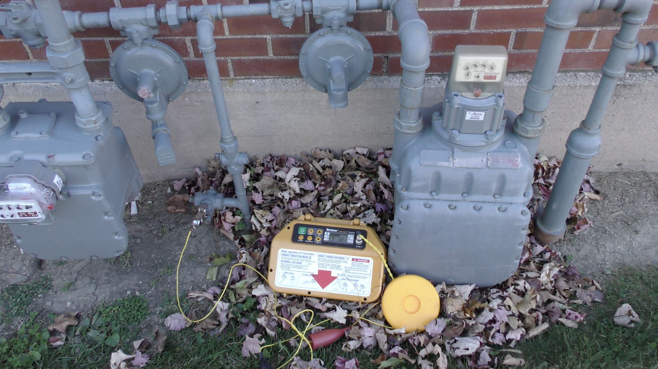
Figure 9
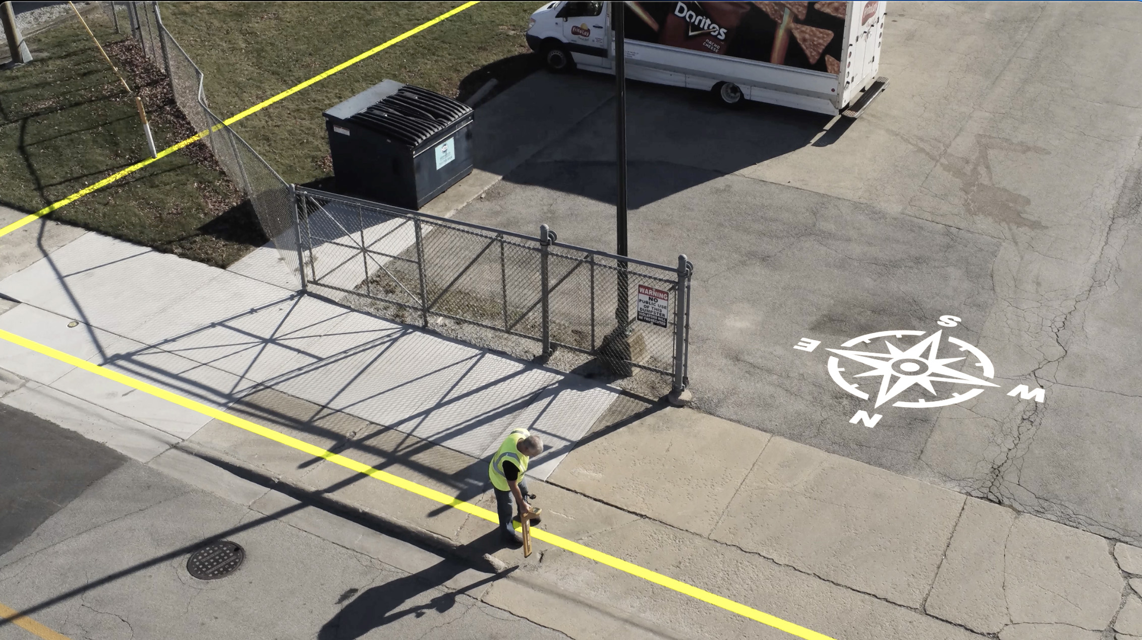
Figure 10
When the instrument is swung to the south (Figure 11), the peak reading numbers are lower than when the instrument is swung to the north (Figure 12). Once more, assuming a symmetrical swing of the receiver, the reason the peak readings are lower to the south is due to destructive interference.
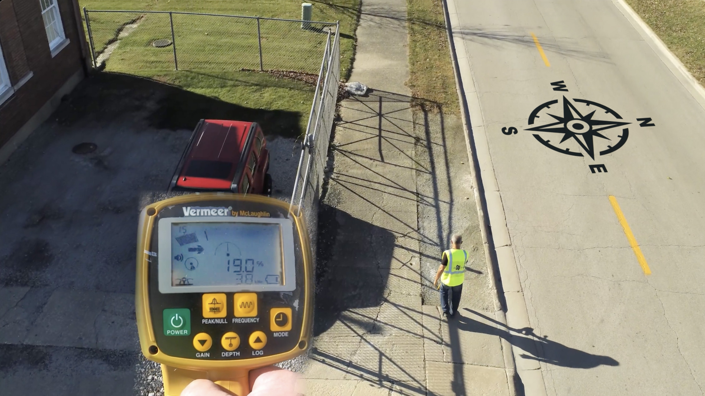
Figure 11
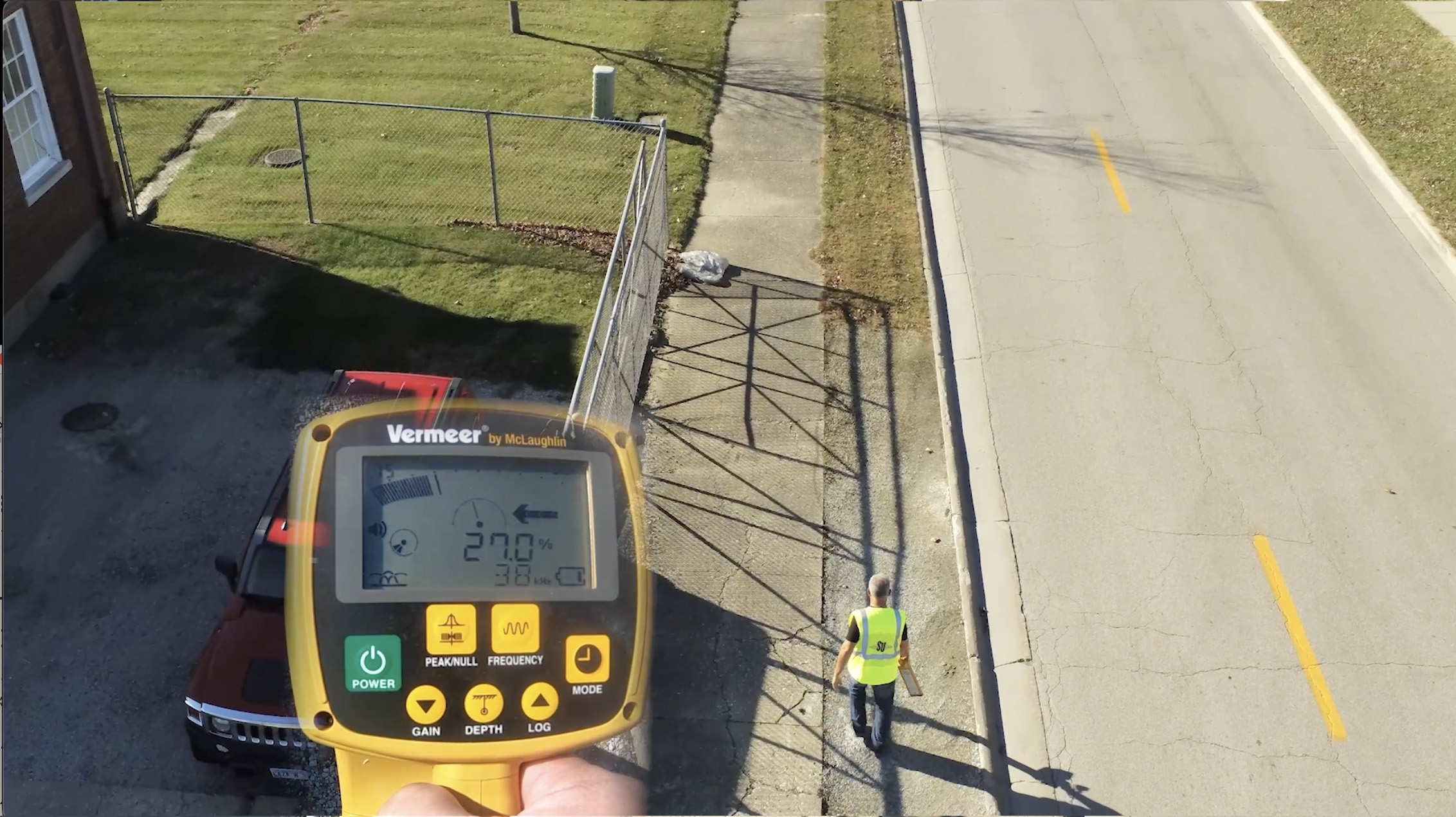
Figure 12
There’s some energy from the transmitter on the cable TV line (Figure 13).
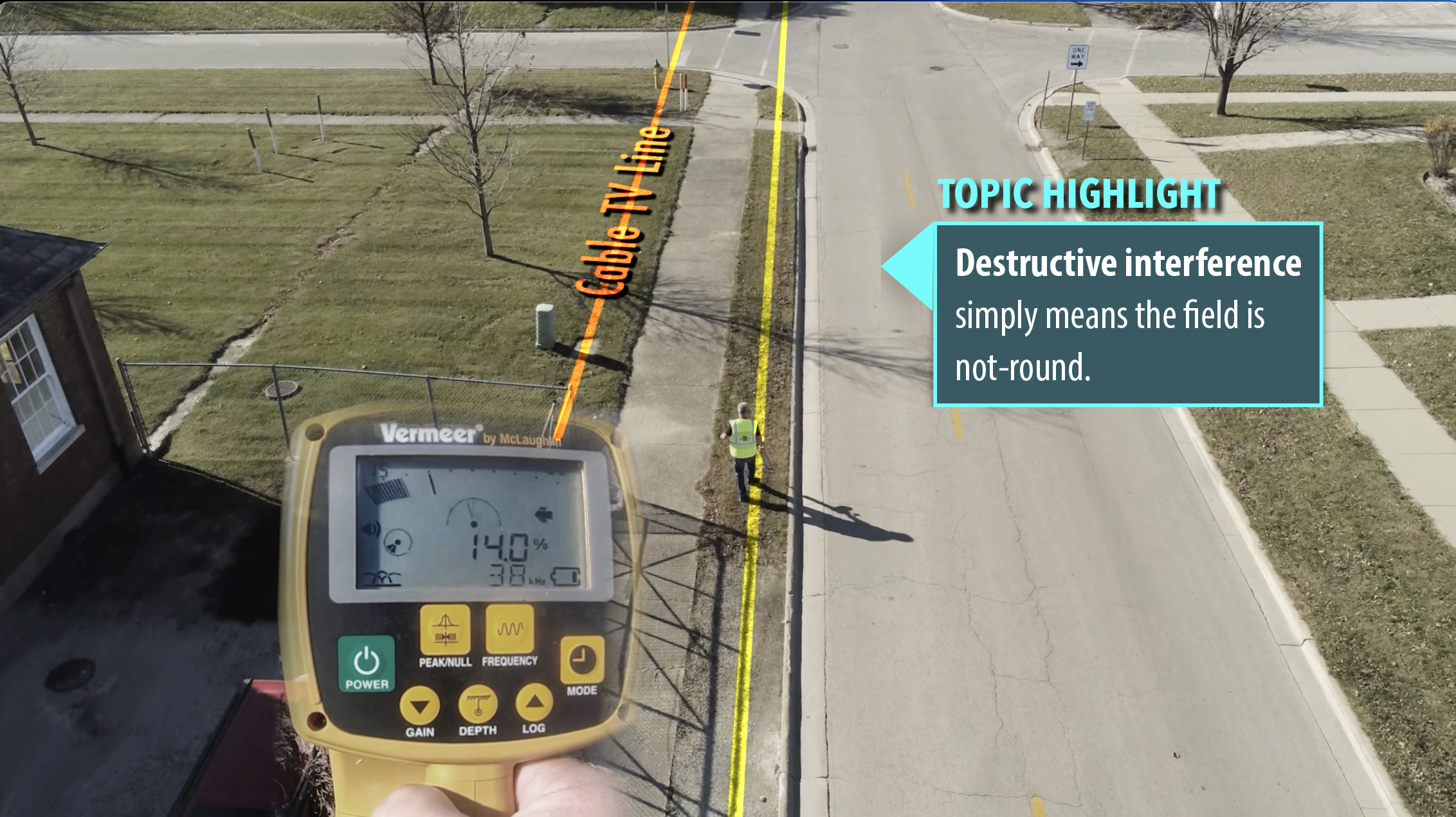
Figure 13
The current on the cable TV line is running in an opposite direction to that on the steel gas main, the target utility. With destructive interference, the lower signal circle value is subtracted from the higher signal circle value (Figures 14-15).
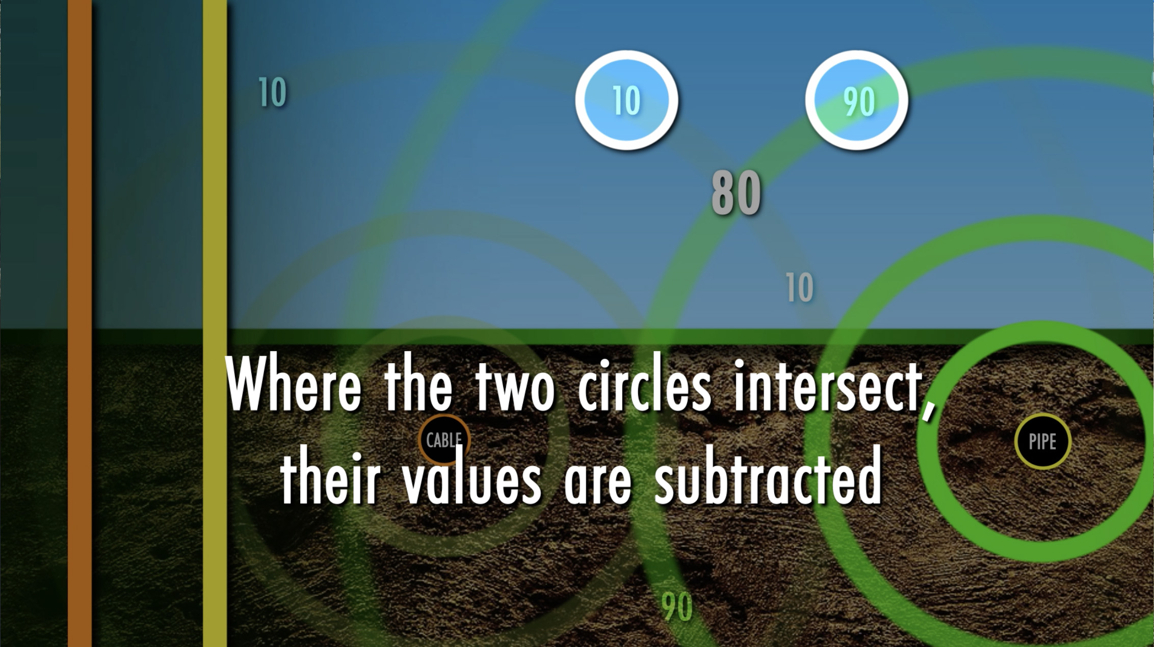
Figure 14
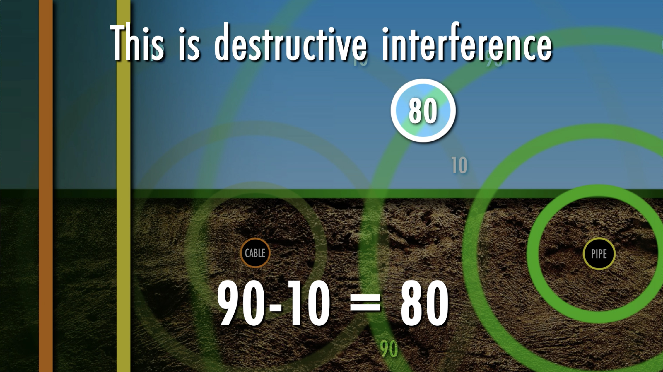
Figure 15
The current on the cable TV line is running in an opposite direction to that on the steel gas main, the target utility (Figure 16).
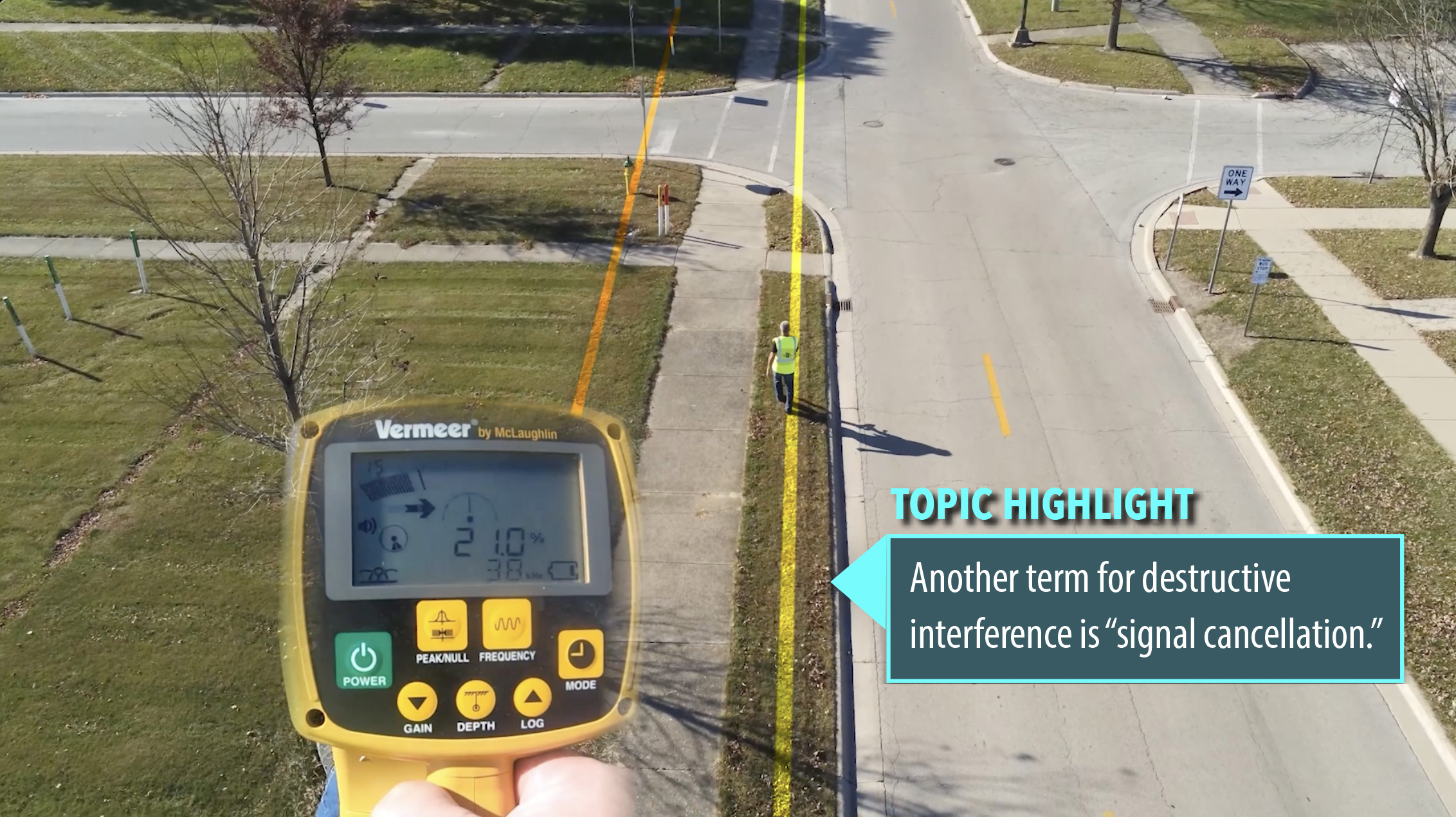
Figure 16
Vertical inspection of the field is utilized to determine the accuracy of your trace. There are three ways in which you can check for the shape of your field in a vertical perspective: peak vs. null, depth validation, and the lift test. The easiest and most efficient method of determining field shape is to compare the peak location to the null location. The most valuable and easiest way to see the shape of the field is to see if peak and null agree or not (Figure 17). If they agree, the signal is round. If they disagree, the signal is not-round.
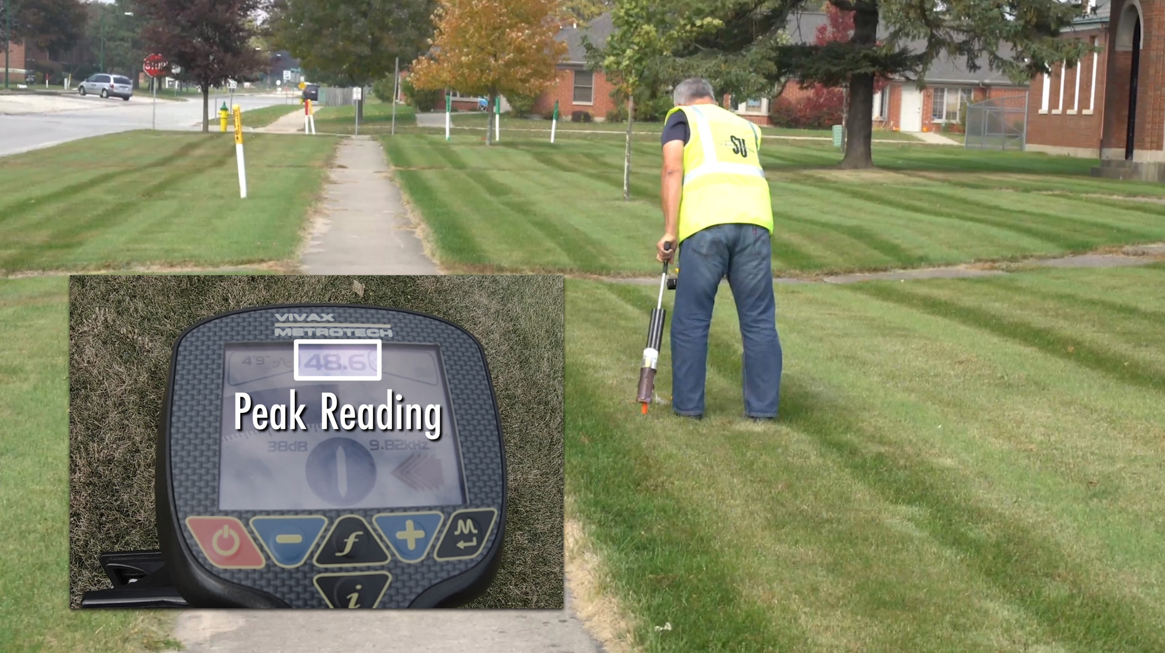
Figure 17
Below, the null is to the west of the peak (Figure 18). Peak and null do not agree, indicating the shape of the field is not-round. The greater the distance between peak and null locations, the greater the degree of destructive or constructive interference.
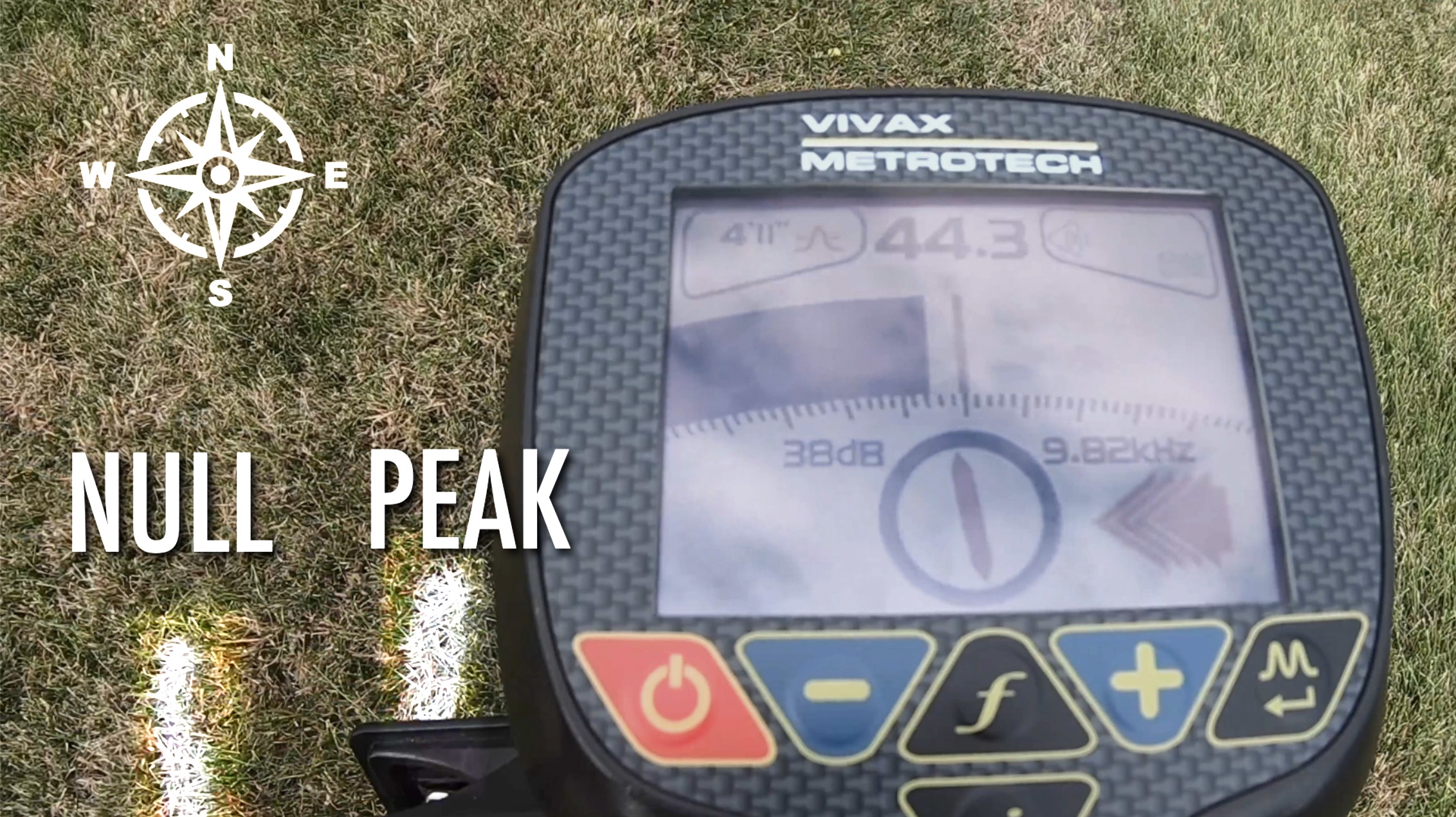
Figure 18
The null is west of the peak with this instrument as well (Figure 19). What causes a not-round field? It’s the presence of the transmitter’s energy on more than just the target line (Figure 20). Comparing peak to null (or peak versus null) is a vertical inspection of the field. Conversely, when peak and null locations agree it’s because no other nearby metallic object is sufficiently energized to affect the accuracy of the trace.
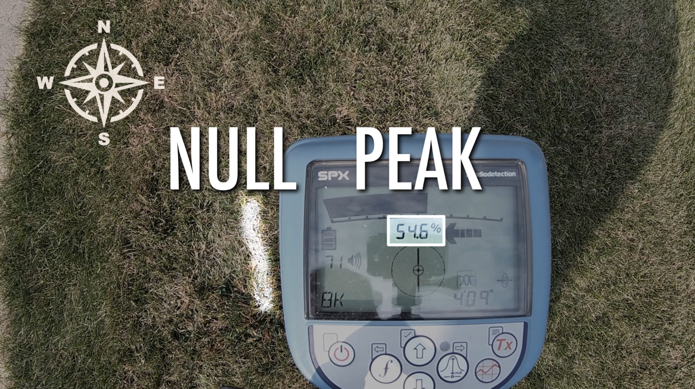
Figure 19
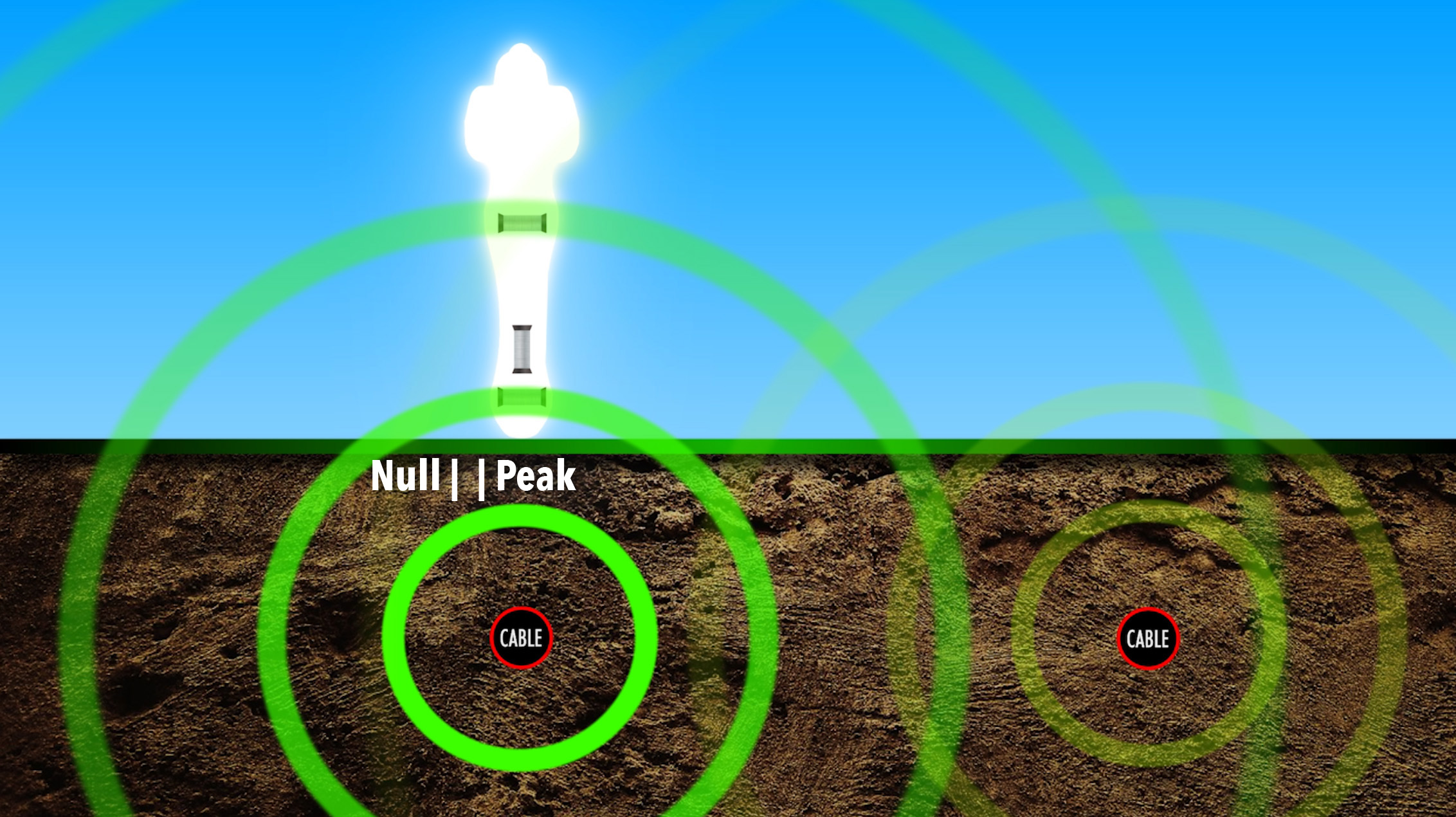
Figure 20
Another method that checks the vertical nature of the field is depth validation. The receiver is raised a known distance, and the new depth reading will either agree with that raised distance or disagree. If it agrees, the field is round. If it disagrees, the field is not-round (Figures 21-22). Digital depth validation is a vertical inspection of the field.
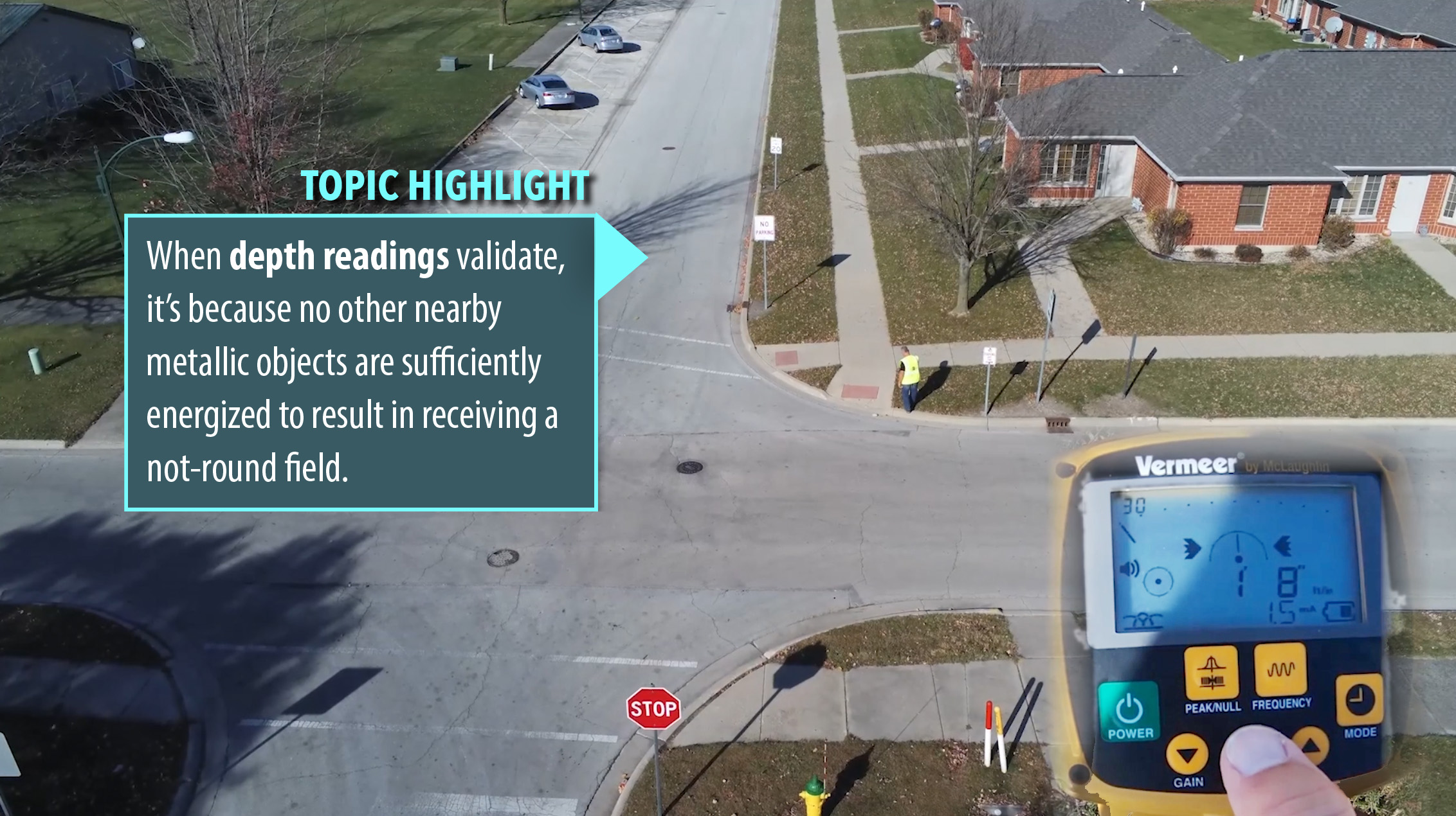
Figure 21
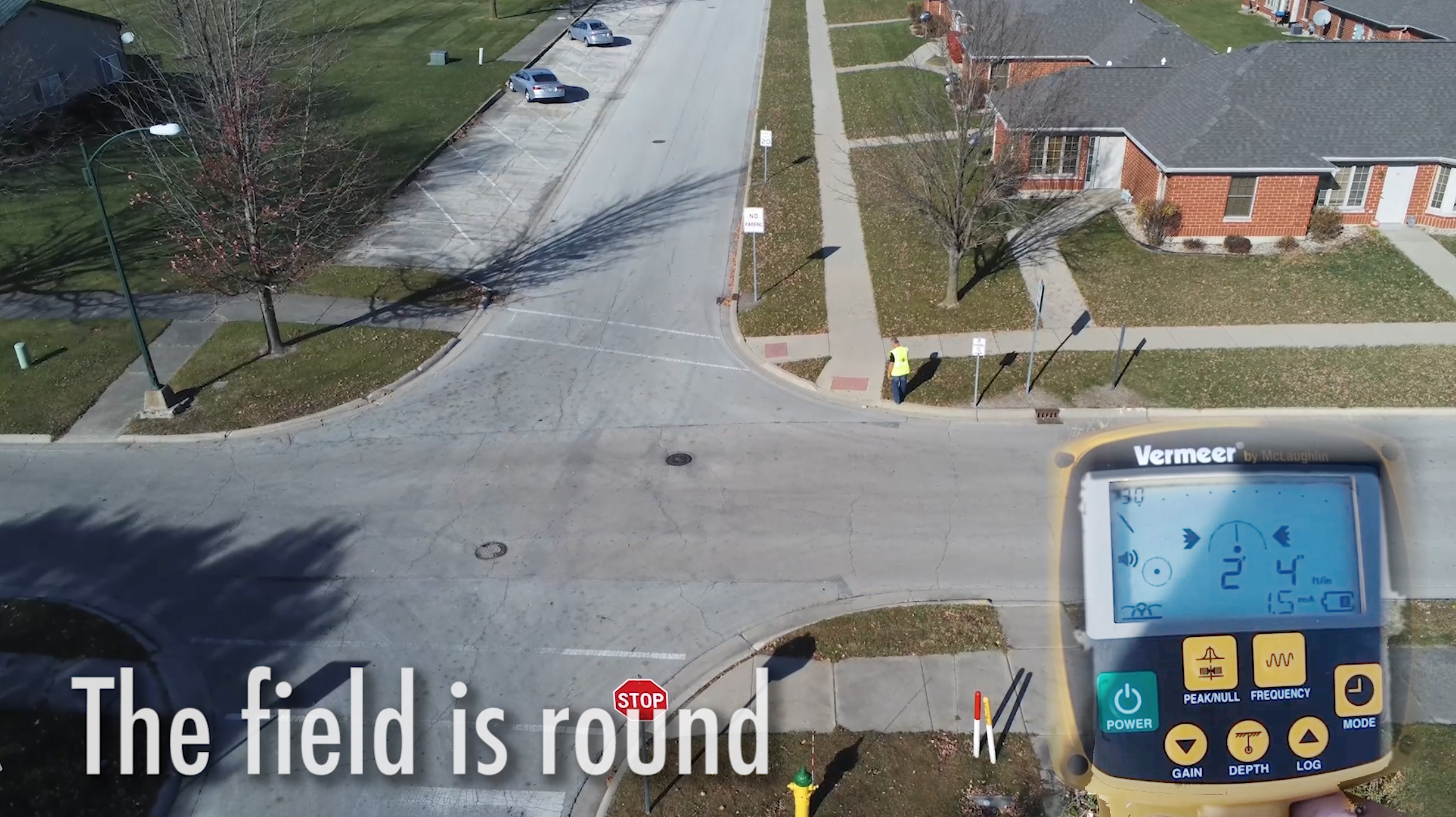
Figure 22
If peak and null disagree, it is unlikely digital depth will validate. However, with the bottom of the receiver placed on the ground, a null arrow will appear if the top of the receiver is moved to the left or the right (Figure 23).
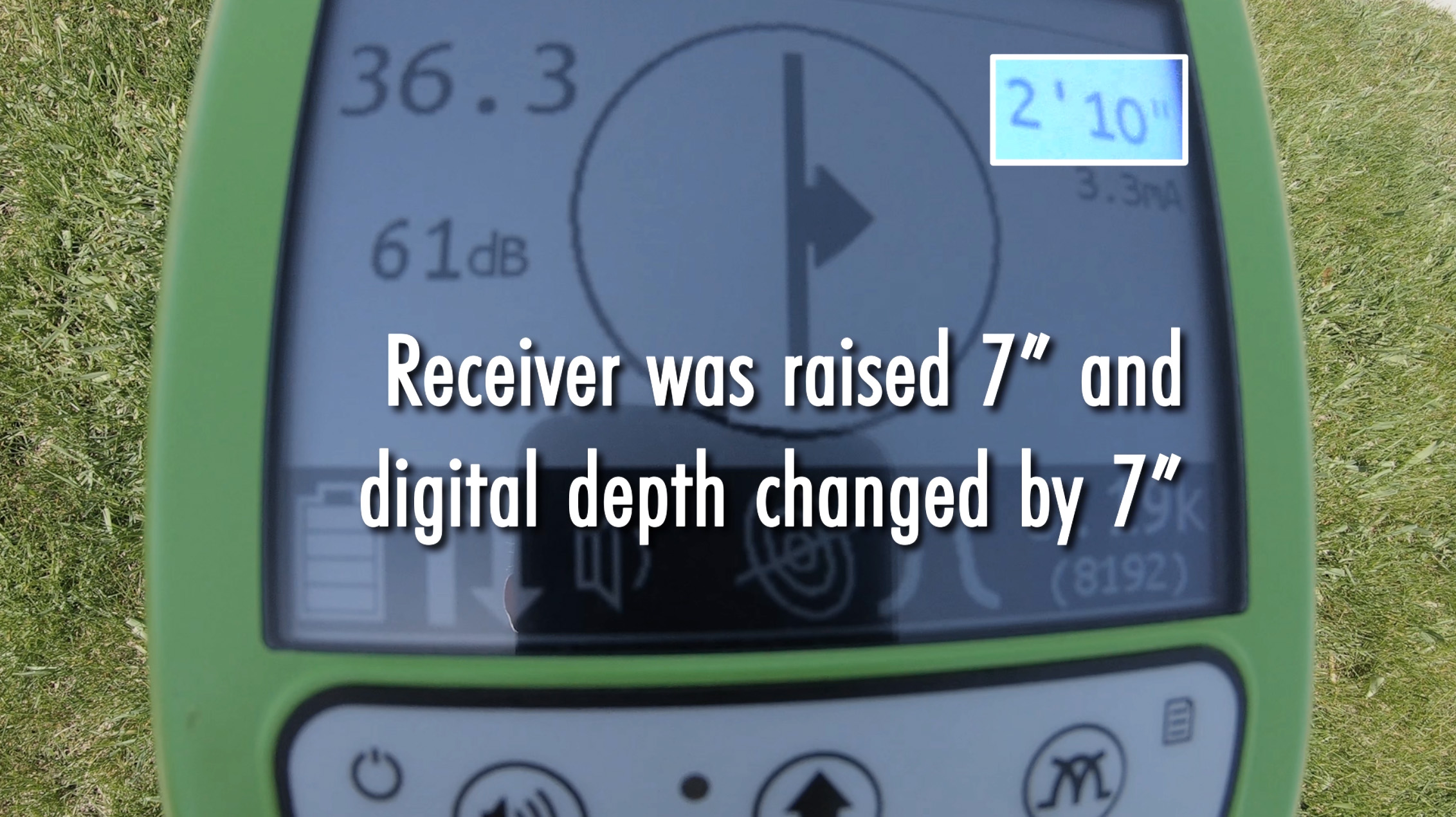
Figure 23
The receiver should be held precisely perpendicular to ground when obtaining depth readings. With a depth of 2’10”, the receiver was raised 7” and the new depth is 3’5” (Figure 24). The field is round.
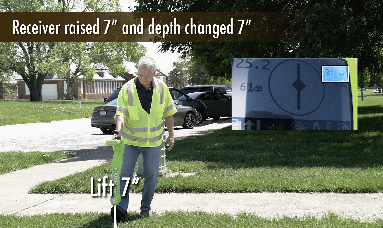
Figure 24
The receiver on the ground indicates a 4’06” reading (Figure 25), and when lifted 7” off the ground gives a reading of 5’01” (Figure 26). This is a round field.
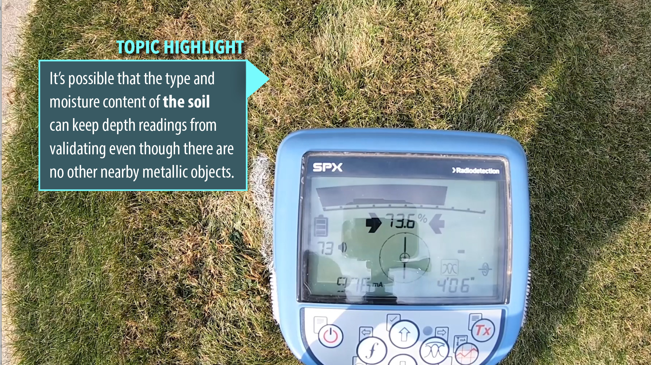
Figure 25
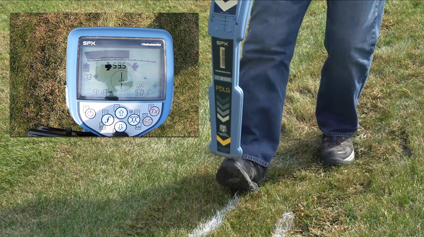
Figure 26
The third and last method of inspecting the field from a vertical perspective involves getting a null reading at the ground and lifting the receiver chest high to see if there’s still a null reading (Figure 27). If there is, the field is round (Figure 28). If there isn’t, the field is not-round.
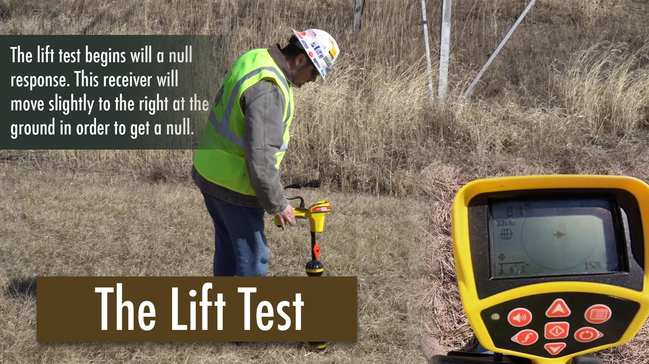
Figure 27
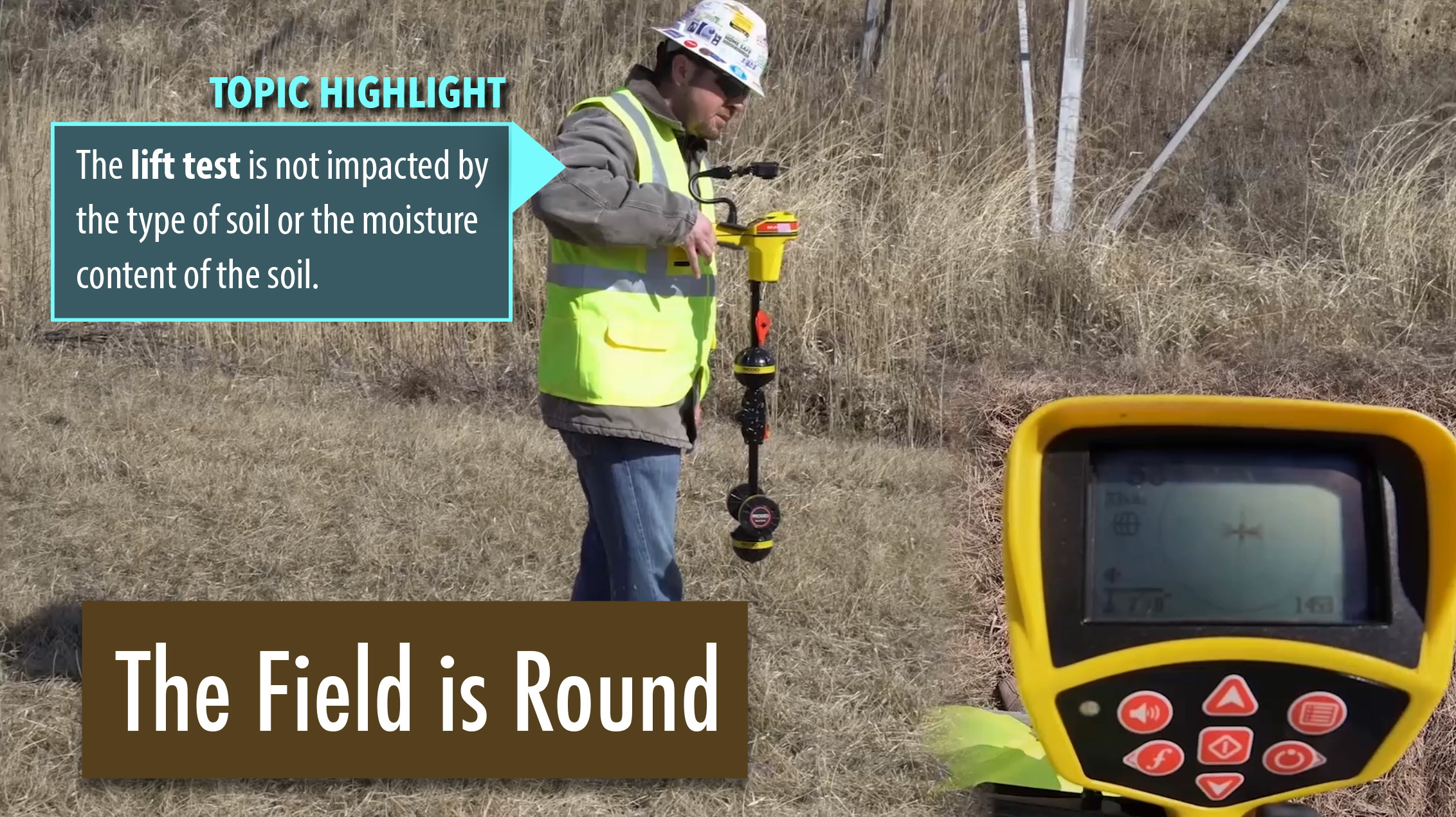
Figure 28
The lift test is a vertical inspection of the field. Using our null reading, we lift the instrument into the air. We don’t have a null reading here, so the field is not-round (Figure 29).
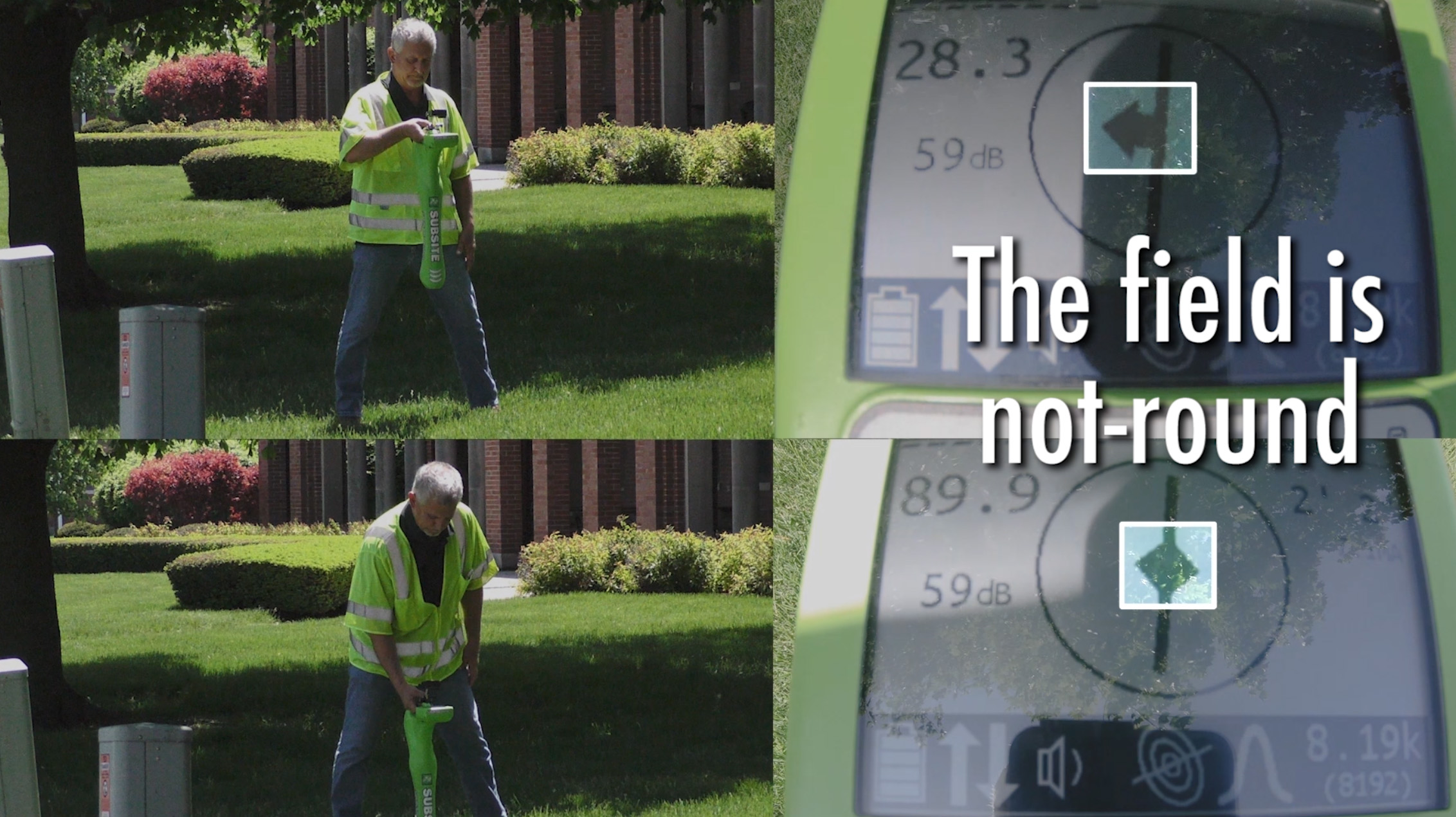
Figure 29
We’ll do a lift test on another line. The instrument should be lifted chest high, but still permitting the display to be read. Here (Figure 30), we had a null on the ground, the starting point for the lift test, and we had a null when we lifted it chest high. This indicates a round field.
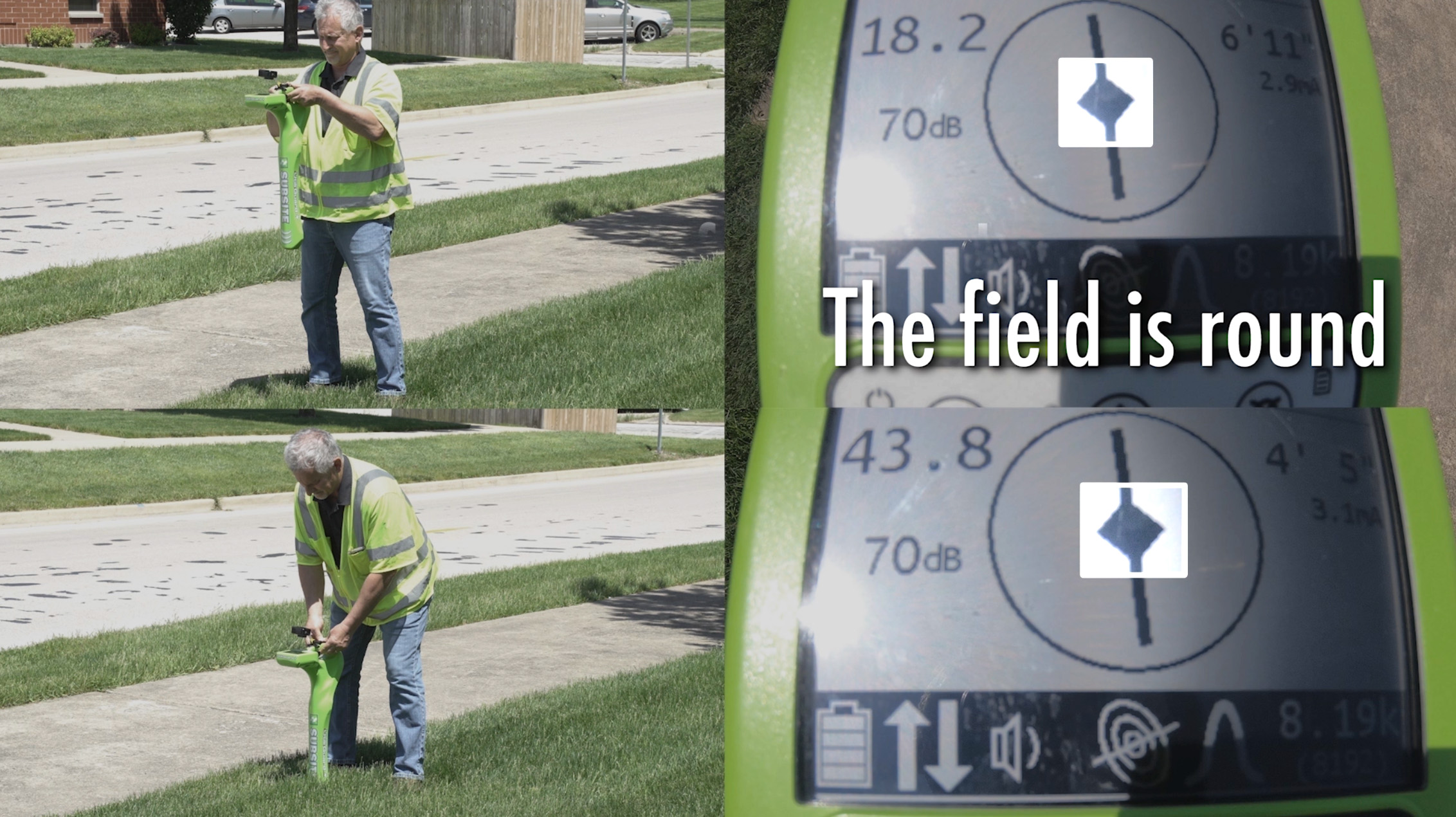
Figure 30
Checking the shape of the field is all about checking the accuracy of the trace. For example, if digital depth validation is way off there’s a chance the line being located is not the target line. The same is true if there’s a good deal of separation between peak and null, or if the null moves a lot when the receiver is lifted chest high. But when vertical inspection of the field indicate smaller differences in locations or depth, the target line is very likely being located but the transmitter’s energy is also on another metallic object, often another underground line. Changing this result means there must be changes at the transmitter.
However, there is a fundamental difference between vertical inspection of the field and horizontal inspection of the field (Figure 31). Determining that a trace is accurate does not require that all five methods of checking field shape need to agree. Vertical inspections and following the trace to a visual and logical endpoint determine target line accuracy. Horizontal inspections are much more valuable as a means to determine what other buried utilities may be in the ground in addition to the target line (Figure 32).
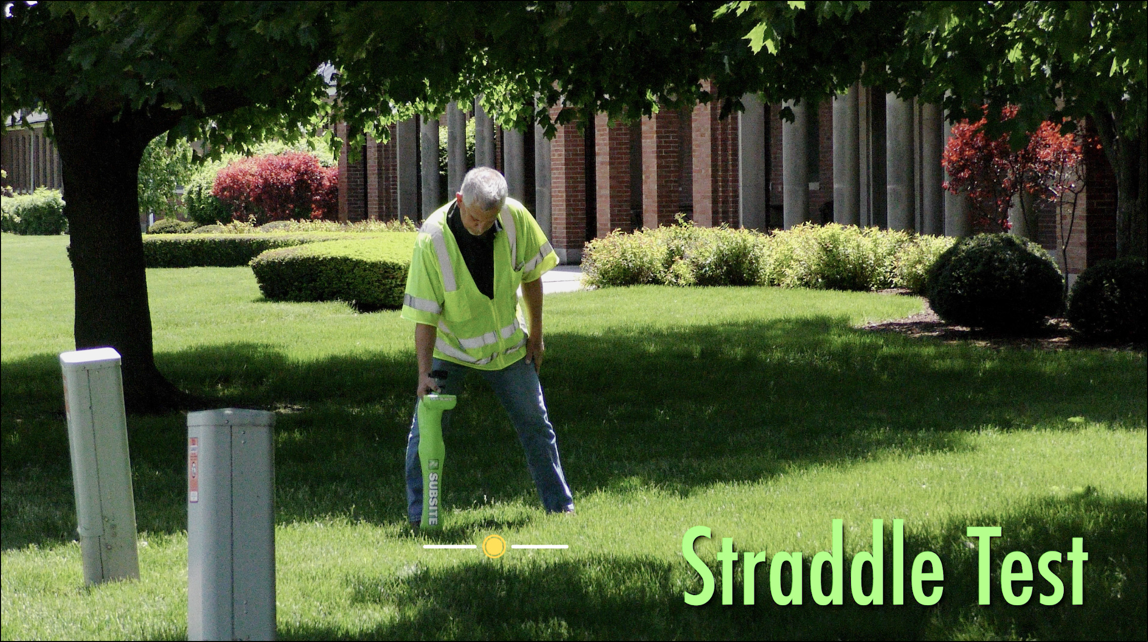
Figure 31
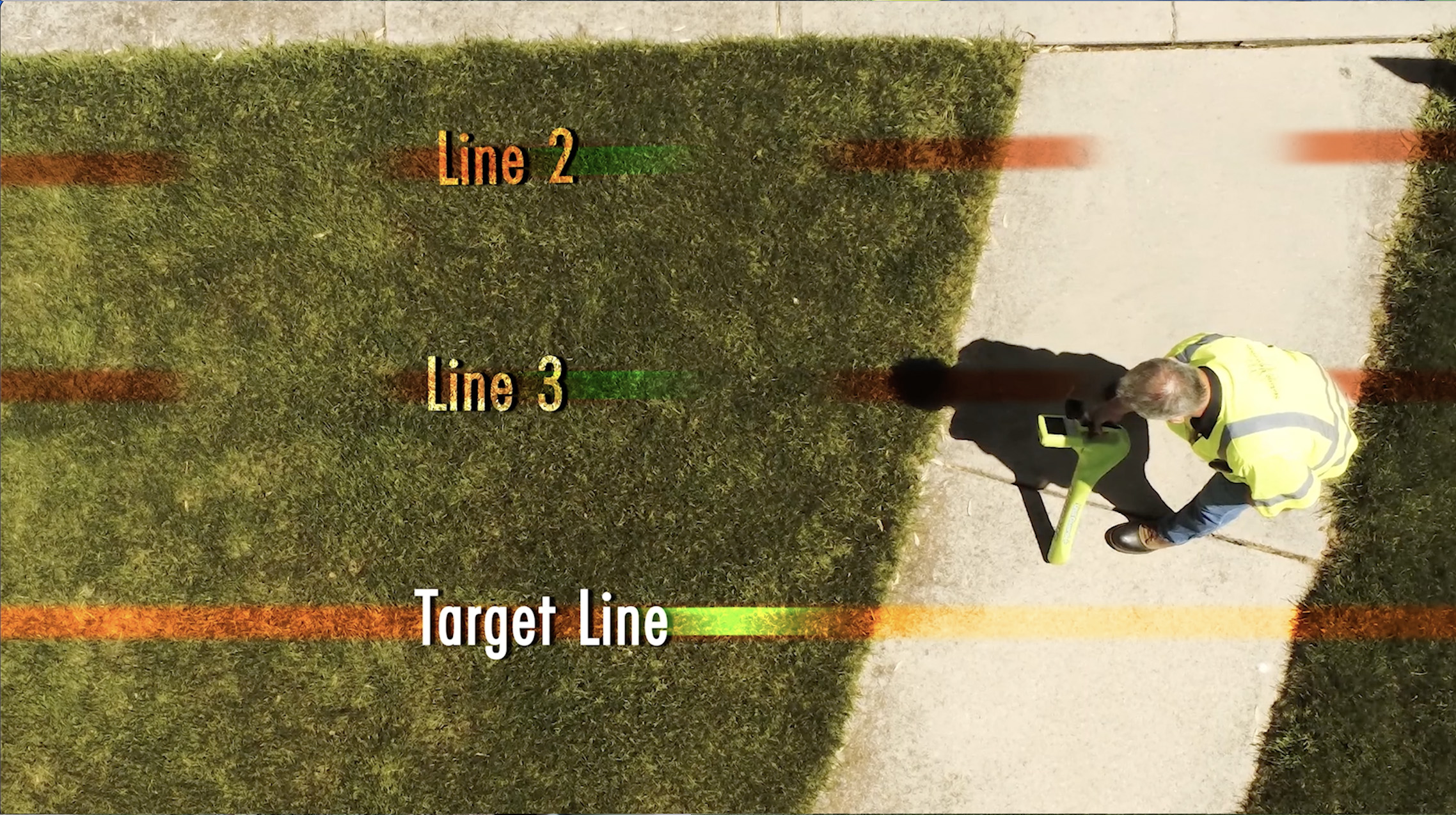
Figure 32
>>>Next Section